24vVR6T CQ Project: EATSGTR rear firewall fab.

Document and share your build!
my2000apb
Posts: 1944
Joined: Fri Mar 01, 2013 11:52 am
Location: CT

Re: 24vVR6T CQ Project: EATSGTR, chassis FAB

Post by my2000apb »

MORE!!
I got the front cross member supports finish welded.
front x member bracing finished.jpg
front x member bracing finished.jpg (1.4 MiB) Viewed 42722 times

front x member bracing finished2.jpg
front x member bracing finished2.jpg (1.12 MiB) Viewed 42722 times

front x member bracing finished3.jpg
front x member bracing finished3.jpg (1.3 MiB) Viewed 42722 times


As well as the 20/24AN radiator inlet/outlets, finish welded in all their glory. Very smooth transitions on the inside of these pieces. Now that the radiator is fully mounted I can make the inlet/out fit for great routing of coolant hoses.
radiator inlet outet 20-24 an welded.jpg
radiator inlet outet 20-24 an welded.jpg (1.46 MiB) Viewed 42722 times
my2000apb
Posts: 1944
Joined: Fri Mar 01, 2013 11:52 am
Location: CT

Re: 24vVR6T CQ Project: EATSGTR, chassis FAB

Post by my2000apb »

I also got a chance to seam seal up the rear inner strut towers.
Now I just need to do the inner wheel wells in the back. It looks soooo much cleaner using grey not the white seen here. Its getting a touch of primer asap

rear inner strut towers sealed.jpg
rear inner strut towers sealed.jpg (1.42 MiB) Viewed 42722 times

rear inner strut towers sealed2.jpg
rear inner strut towers sealed2.jpg (1.29 MiB) Viewed 42722 times

rear inner strut towers sealed3.jpg
rear inner strut towers sealed3.jpg (1.33 MiB) Viewed 42722 times
my2000apb
Posts: 1944
Joined: Fri Mar 01, 2013 11:52 am
Location: CT

Re: 24vVR6T CQ Project: EATSGTR, chassis FAB

Post by my2000apb »

UPDATE!!!
I drew up some water/methanol nozzle bungs and had them machined up by a friend. They are 1/8”-27 NPT. The inner end radius exactly matches the inner end radius of the Ross Machine oval tubing.
water methanol bungs machined.jpg
water methanol bungs machined.jpg (1.77 MiB) Viewed 42722 times

water methanol bungs machined2.jpg
water methanol bungs machined2.jpg (1.85 MiB) Viewed 42722 times

water methanol bungs machined3.jpg
water methanol bungs machined3.jpg (1.09 MiB) Viewed 42722 times
my2000apb
Posts: 1944
Joined: Fri Mar 01, 2013 11:52 am
Location: CT

Re: 24vVR6T CQ Project: EATSGTR, chassis FAB

Post by my2000apb »

More. I got the intake manifold runners all drilled and prepped for bung welding.
water methanol IM holes for bungs.jpg
water methanol IM holes for bungs.jpg (1.28 MiB) Viewed 42722 times

water methanol bungs ready to weld.jpg
water methanol bungs ready to weld.jpg (1.55 MiB) Viewed 42722 times


I used a piece of solid stock 1.25” the put down in the runner so the bung will sit evenly and flush in the runner when its finish welded. It just needs final texture/smoothing before the plenum is welded on. See pic
water meth bungs- in-runner radius detail.jpg
water meth bungs- in-runner radius detail.jpg (1.95 MiB) Viewed 42722 times


And here they are all welded on.
water methanol bungs finish welded.jpg
water methanol bungs finish welded.jpg (1.92 MiB) Viewed 42722 times
DE80q
Posts: 2572
Joined: Mon Mar 04, 2013 9:25 am
Location: York PA 17403

Re: 24vVR6T CQ Project: EATSGTR, chassis FAB

Post by DE80q »

Woot! looking good!
"If you can't find one, make one"

Dallastown, PA
1991 Audi 80 quattro (20vt project)
1991 Audi Coupe Quattro (project: my first 20v)
2007 Mitsubishi Raider(Dakota in disguise)
2019 Chevy Cruze RS hatch (wife's little red sporty car)
my2000apb
Posts: 1944
Joined: Fri Mar 01, 2013 11:52 am
Location: CT

Re: 24vVR6T CQ Project: EATSGTR, chassis FAB

Post by my2000apb »

UPDATE!!!
Ok lets get caught up!

I got a lot of time over the Christmas/ new year holiday period to work on the car.

I used a hole saw and some carbide action to make some IC breathing holes in my front x-member. There’s no use having a massive intercooler if its not all getting air, so now it is!!

The holes will be flappered down and smoothed.
Here they are prepped to weld
IC fresh air holes prepped2.jpg
IC fresh air holes prepped2.jpg (1.37 MiB) Viewed 42670 times


Here they are all welded up.
IC fresh air holes welded.jpg
IC fresh air holes welded.jpg (1.27 MiB) Viewed 42670 times

IC fresh air holes welded2.jpg
IC fresh air holes welded2.jpg (1.61 MiB) Viewed 42670 times

IC mount fresh air holes welded3.jpg
IC mount fresh air holes welded3.jpg (1.65 MiB) Viewed 42670 times
my2000apb
Posts: 1944
Joined: Fri Mar 01, 2013 11:52 am
Location: CT

Re: 24vVR6T CQ Project: EATSGTR, chassis FAB

Post by my2000apb »

I also added sleeves in the rect. Tube for the IC mounting screws. It’ll be nice not losing the IC mount bolt in the inside of the brace each time I take it off/on hahah.
IC mount through holes welded.jpg
IC mount through holes welded.jpg (1.72 MiB) Viewed 42669 times

IC mount through holes welded2.jpg
IC mount through holes welded2.jpg (1.68 MiB) Viewed 42669 times


I also added some mounts for dzus fastener plates at the front of the cross member, these are to retain the belly pan I will be making.
belly pan mounts.jpg
belly pan mounts.jpg (1.4 MiB) Viewed 42669 times

belly pan mounts detail.jpg
belly pan mounts detail.jpg (1.56 MiB) Viewed 42669 times
my2000apb
Posts: 1944
Joined: Fri Mar 01, 2013 11:52 am
Location: CT

Re: 24vVR6T CQ Project: EATSGTR, chassis FAB

Post by my2000apb »

MORE!!
With the driver and passenger seats moved quite rearward, I needed to make a passenger side footrest. There will also be a small, false-floor built in for a heel rest.

Here it is framed out.
passenger footrest frame.jpg
passenger footrest frame.jpg (1.95 MiB) Viewed 42669 times


Note the jigsaw construction.
passenger footrest frame jigsaw.jpg
passenger footrest frame jigsaw.jpg (1.42 MiB) Viewed 42669 times

passenger footrest frame jigsaw2.jpg
passenger footrest frame jigsaw2.jpg (1.36 MiB) Viewed 42669 times
my2000apb
Posts: 1944
Joined: Fri Mar 01, 2013 11:52 am
Location: CT

Re: 24vVR6T CQ Project: EATSGTR, chassis FAB

Post by my2000apb »

Skinned in 0.063” 6061
pass footrest skinning.jpg
pass footrest skinning.jpg (1.46 MiB) Viewed 42668 times

pass footrest skinning backside.jpg
pass footrest skinning backside.jpg (1.44 MiB) Viewed 42668 times


And finally here it is with dimple die holes, they add sooo much rigidity it’s incredible.
pass footrest with dimple die holes.jpg
pass footrest with dimple die holes.jpg (1.98 MiB) Viewed 42668 times

pass footrest with dimple die holes backside.jpg
pass footrest with dimple die holes backside.jpg (1.87 MiB) Viewed 42668 times


in place, well about
pass footrest mockup inplace.jpg
pass footrest mockup inplace.jpg (1.29 MiB) Viewed 42668 times
my2000apb
Posts: 1944
Joined: Fri Mar 01, 2013 11:52 am
Location: CT

Re: 24vVR6T CQ Project: EATSGTR, chassis FAB

Post by my2000apb »

UPDATE!!!
I finally tore back into the re-doing of the driver’s side engine mount arm. There was nothing really “wrong” with the first version, but it was made to be replaced haaha and utilized the oem accessory bracket. I have no use for this oem bracket, as im only running an alternator and we cut off the ALT mount to fit the intake manifold haha, so ground up remodel had to happen

engine mount soon to be redone.jpg
engine mount soon to be redone.jpg (1.32 MiB) Viewed 42667 times


Templates being made
engine mount arm remake in alu templates.jpg
engine mount arm remake in alu templates.jpg (1.24 MiB) Viewed 42667 times


Ready for some welding.
engine mount arm coming together.jpg
engine mount arm coming together.jpg (1.13 MiB) Viewed 42667 times

engine mount arm coming together2.jpg
engine mount arm coming together2.jpg (1.26 MiB) Viewed 42667 times

engine mount arm coming together3.jpg
engine mount arm coming together3.jpg (1.35 MiB) Viewed 42667 times
my2000apb
Posts: 1944
Joined: Fri Mar 01, 2013 11:52 am
Location: CT

Re: 24vVR6T CQ Project: EATSGTR, chassis FAB

Post by my2000apb »

Here it is welded together
engine mount arm welded.jpg
engine mount arm welded.jpg (1.08 MiB) Viewed 42670 times

engine mount arm welded2.jpg
engine mount arm welded2.jpg (1.11 MiB) Viewed 42670 times


Its getting to look like a mount arm
drivers side eng arm gettign there.jpg
drivers side eng arm gettign there.jpg (1.29 MiB) Viewed 42670 times

drivers side eng arm gettign there2.jpg
drivers side eng arm gettign there2.jpg (1.3 MiB) Viewed 42670 times


Front portion mount plates
drivers eng mount plates.jpg
drivers eng mount plates.jpg (1.39 MiB) Viewed 42670 times
my2000apb
Posts: 1944
Joined: Fri Mar 01, 2013 11:52 am
Location: CT

Re: 24vVR6T CQ Project: EATSGTR, chassis FAB

Post by my2000apb »

MORE!!! Mockup/temp. alternator and idler pulley mounting. Ryan is machining me some exact pieces to help keep everything right on-plane, as it should be
ALT and tensioner mount.jpg
ALT and tensioner mount.jpg (1.55 MiB) Viewed 42668 times

ALT and tensioner mount2.jpg
ALT and tensioner mount2.jpg (1.74 MiB) Viewed 42668 times


The front/upper support is getting a plug weld to its plate for add’l strength.
plug weld post for upperfront support.jpg
plug weld post for upperfront support.jpg (1.71 MiB) Viewed 42668 times

plug weld post for upperfront support backside.jpg
plug weld post for upperfront support backside.jpg (1.79 MiB) Viewed 42668 times
my2000apb
Posts: 1944
Joined: Fri Mar 01, 2013 11:52 am
Location: CT

Re: 24vVR6T CQ Project: EATSGTR, chassis FAB

Post by my2000apb »

And here is the idler mount being machined, its going to be gusseted as well. It is quite strong and sits just out of the way of the alternator.

tensioner mount machining.jpg
tensioner mount machining.jpg (1.77 MiB) Viewed 42668 times

tensioner mount machining2.jpg
tensioner mount machining2.jpg (1.89 MiB) Viewed 42668 times

tensioner mount finished.jpg
tensioner mount finished.jpg (1.13 MiB) Viewed 42668 times

tensioner mount finished2.jpg
tensioner mount finished2.jpg (1.21 MiB) Viewed 42668 times

tensioner mount finished3.jpg
tensioner mount finished3.jpg (1.04 MiB) Viewed 42668 times
my2000apb
Posts: 1944
Joined: Fri Mar 01, 2013 11:52 am
Location: CT

Re: 24vVR6T CQ Project: EATSGTR, chassis FAB

Post by my2000apb »

MORE!!

Upper mount arm plug weld is done!
plug weld, upper done.jpg
plug weld, upper done.jpg (1.83 MiB) Viewed 42667 times


I got my machined bits back from ryan, the idler mount and alternator through bolt mount are done and ready for install.
ALT bracket from above.jpg
ALT bracket from above.jpg (1.39 MiB) Viewed 42667 times


The alt. mount piece is cut from a large T shaped piece of stock, so we can put the through bolt as close or far from the block as we want as well as use the “T” legs to give it a larger/stronger footprint on the lower mount plate.

And through bolt clearances front and rearward
Alt bracket bolt relief from rear.jpg
Alt bracket bolt relief from rear.jpg (1.19 MiB) Viewed 42667 times

ALT bracket bolt relief from front.jpg
ALT bracket bolt relief from front.jpg (1.42 MiB) Viewed 42667 times
my2000apb
Posts: 1944
Joined: Fri Mar 01, 2013 11:52 am
Location: CT

Re: 24vVR6T CQ Project: EATSGTR, chassis FAB

Post by my2000apb »

MORE!!
All the pieces are ready for final welding.

The alt mount and tensioner mount are both drilled and tapped and mounted to the bac of the plate with m6x1mm bolts. They are very hand tight haha, so I can align them, but still tight enough that they don’t move if I let go of them.
ALT mount and tesnioner installed.jpg
ALT mount and tesnioner installed.jpg (1.4 MiB) Viewed 42681 times

ALT and tensioner installed.jpg
ALT and tensioner installed.jpg (1.52 MiB) Viewed 42681 times


Haydn hooked it up bigtime!!! He let me borrow his Dayco accessory belt laser alignment tools!!!!!!!! These things are sweeeet. One is curved and relieved to sit in the serp pulley grooves, and has a laser line that goes across the other pullies. We got them spot on!!! Thanks again
And some pics!

dayco pulley alignment tool.jpg
dayco pulley alignment tool.jpg (1.37 MiB) Viewed 42681 times


dayco pulley alignment tool2.jpg
dayco pulley alignment tool2.jpg (1.06 MiB) Viewed 42681 times
my2000apb
Posts: 1944
Joined: Fri Mar 01, 2013 11:52 am
Location: CT

Re: 24vVR6T CQ Project: EATSGTR, chassis FAB

Post by my2000apb »

UPDATE!!!!!!!!!

Ok once again let’s get caught back up to the work that has been completed.
As per requested by others hahah

death 4kqt wrote:header porn is the best


timmmy wrote:MORE.... lets get to the good stuff already :P


Ok, ok, I got it hahahaha

Well here she is!!!

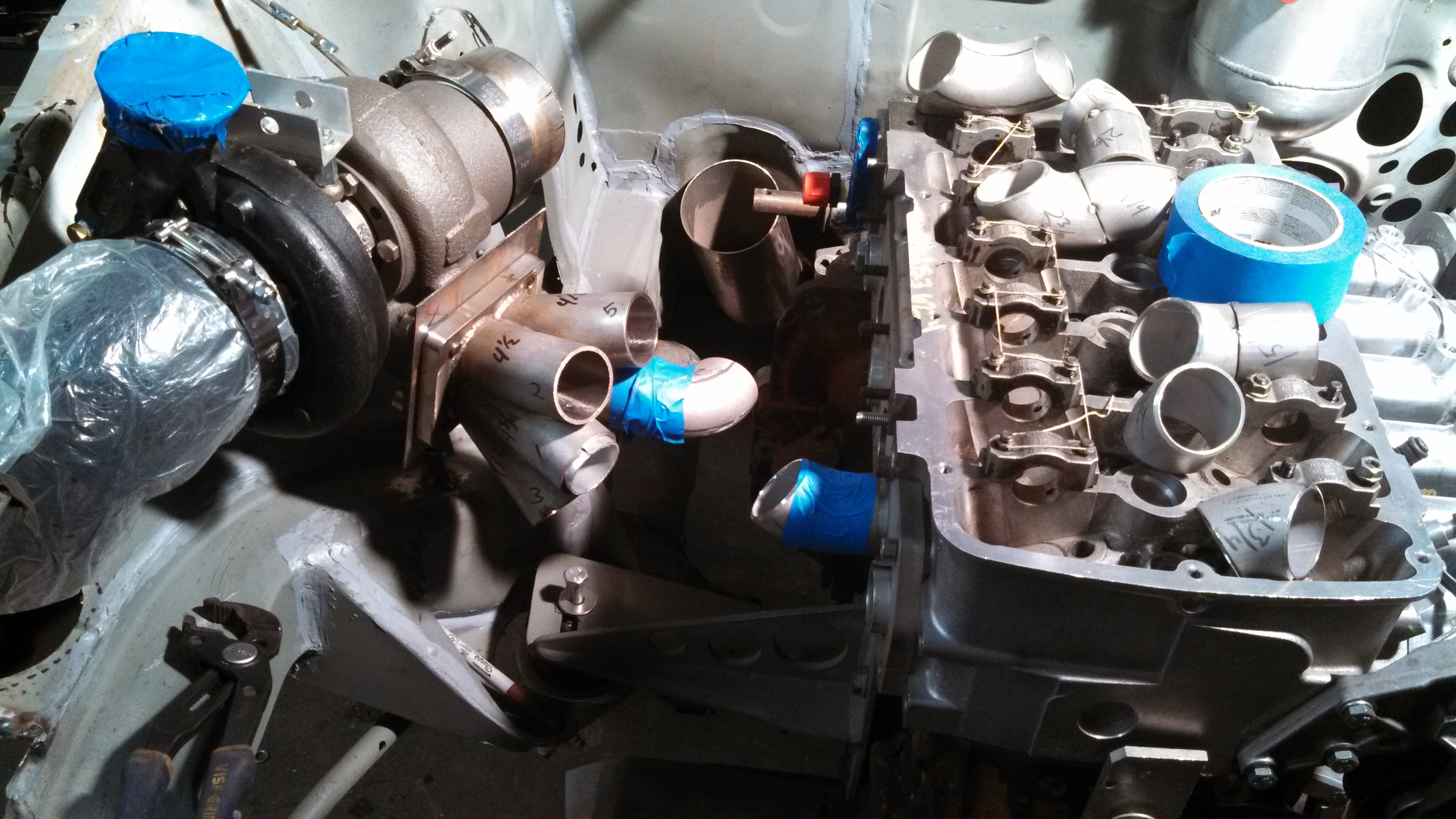
I’ve had the manifold collector seam welded in and out for a while now, and now that I have a ton of weld-els, it’s time to dig right in and get to building.

The collector has been seam welded inside and out, completely. And with that mostly polished up, its runner time!

Based on the vr6 firing order, the front three cylinders and the rear three get paired together for the divided manifold. This saves me a lot of headache in regards to making the runners equal length.

So, I made all the runners, mostly based on smooth flow. The center line lengths have been calc’d from the centerline radius numbers that Vibrant provides.
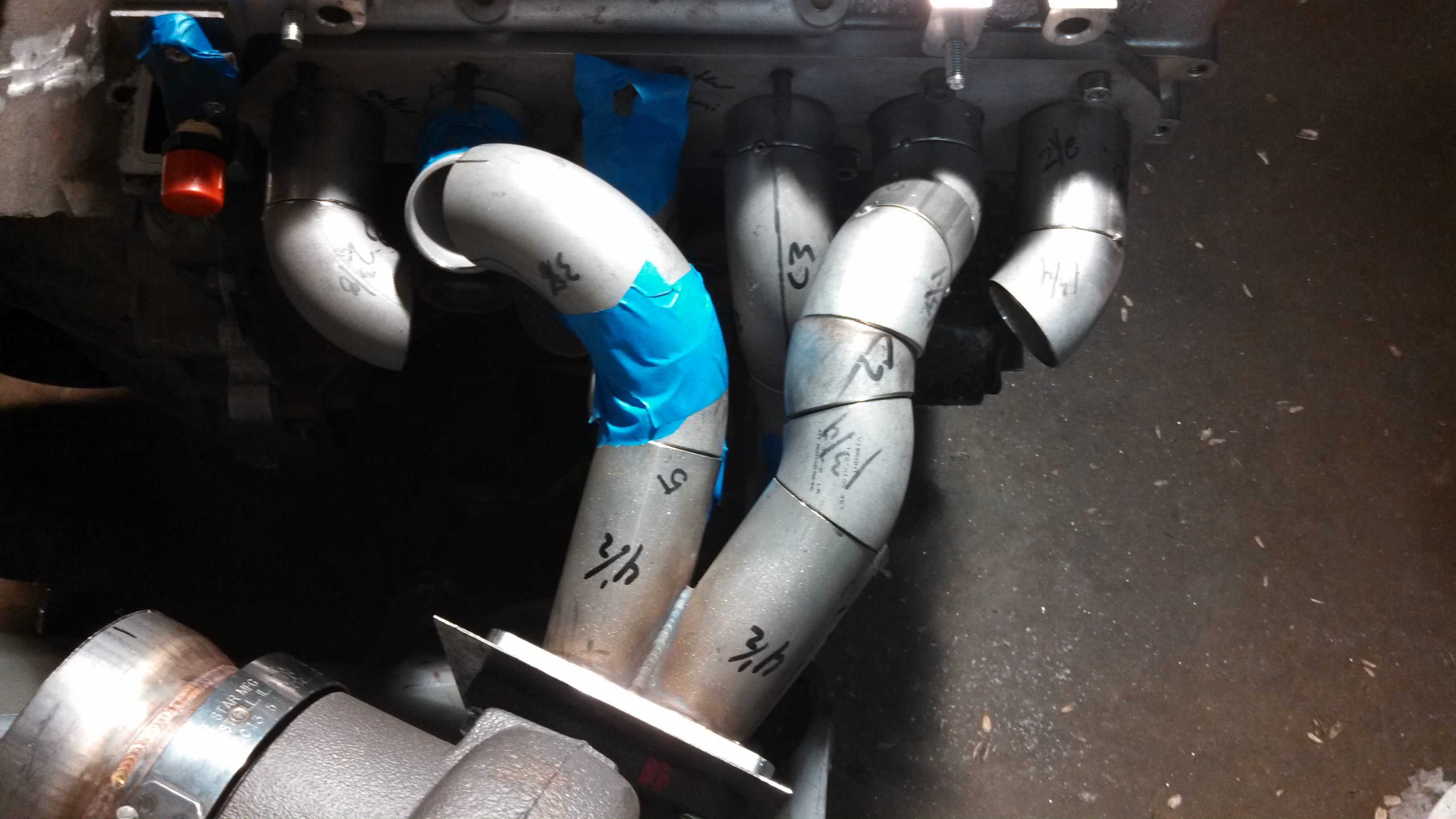
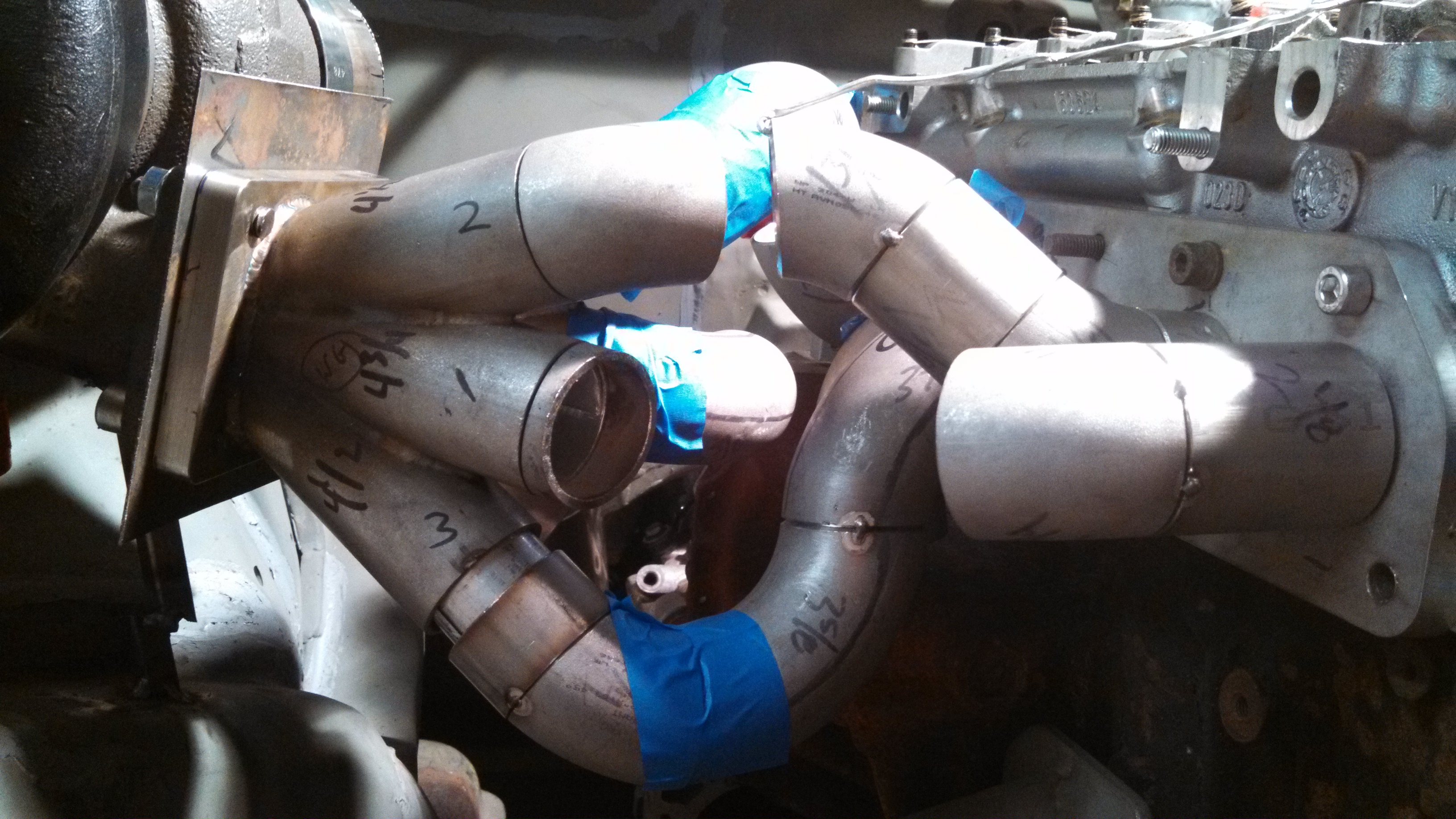
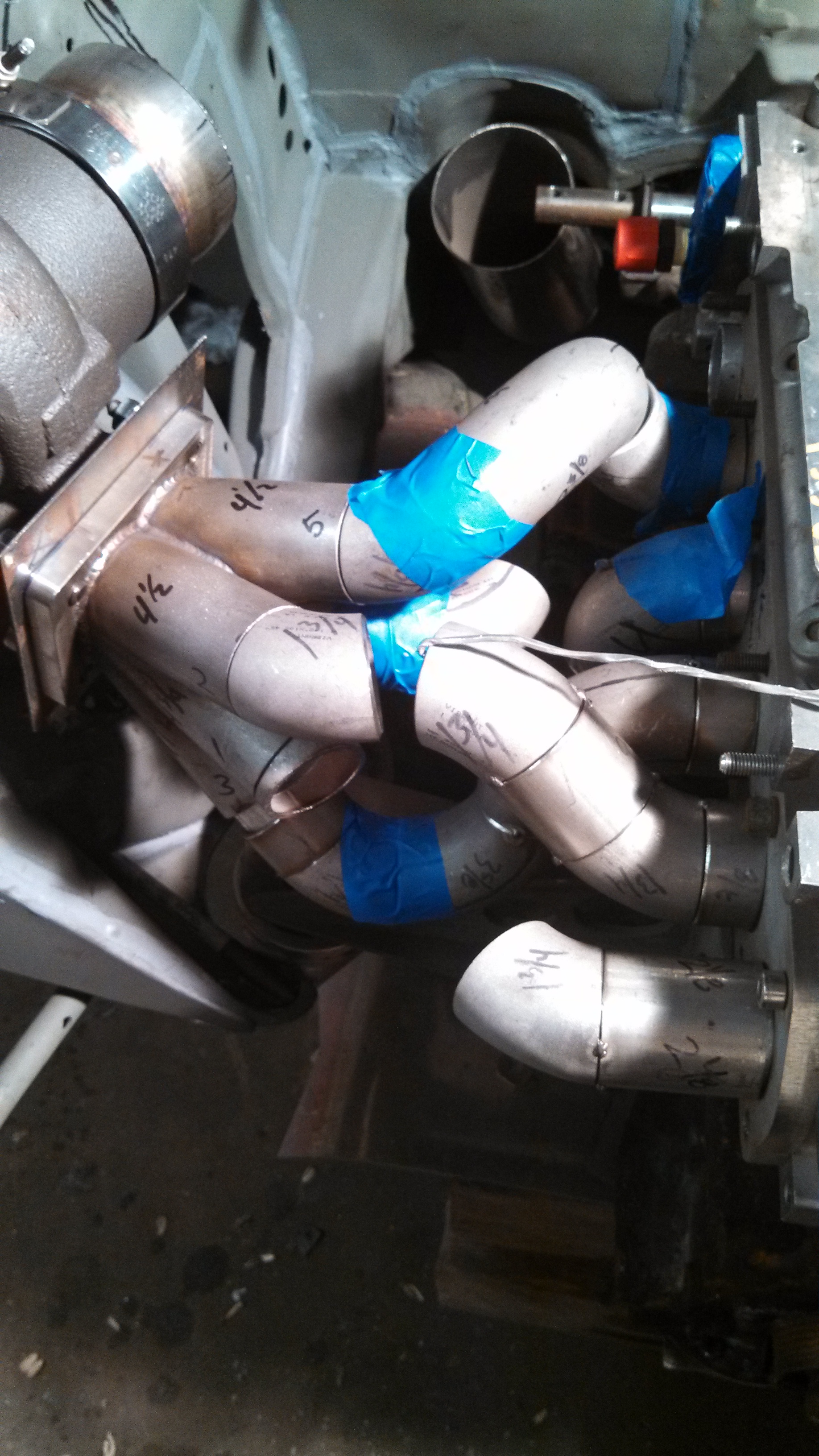
ROUND 1 pictures
EM rd1 getting started.jpg
EM rd1 getting started.jpg (1.98 MiB) Viewed 42592 times

EM rd1 adding pieces.jpg
EM rd1 adding pieces.jpg (1.48 MiB) Viewed 42592 times

EM rd1 getting there.jpg
EM rd1 getting there.jpg (1.85 MiB) Viewed 42592 times

EM rd1 getting there addl angle.jpg
EM rd1 getting there addl angle.jpg (1.67 MiB) Viewed 42592 times


the 3,4,5 runners are all right around mid 14”, the 1,2 and 6 runners were about 15 ½”, 16” and almost 17” respectively. That was not going to work for me so I cut half the manifold back up. It looked all cool first go around, but cutting it up, while dishearteneing is something that needs to be done to make it better hahahaa.
my2000apb
Posts: 1944
Joined: Fri Mar 01, 2013 11:52 am
Location: CT

Re: 24vVR6T CQ Project: EATSGTR, chassis FAB

Post by my2000apb »

MORE!! So I cut a few of the runners off and set to making them shorter. I want all the runner lengths to be a close in length as possible. So I changed them around and set to re-calc’ing the center line lengths. Closer but not close enough, they are now within about 1.5” of each other, not good enough. So I cut it back apart!

ROUND 2 pics!!
And here she is in all her glory!!!!!!!!!!
So its tacked together, awaiting finish seaming and backpurging at Higbee Fab.

EM rd2 above.jpg
EM rd2 above.jpg (1.81 MiB) Viewed 42592 times

EM rd2 above2.jpg
EM rd2 above2.jpg (1.54 MiB) Viewed 42592 times

EM rd2 jsut gotta do #3.jpg
EM rd2 jsut gotta do #3.jpg (1.62 MiB) Viewed 42592 times

EM finish tacked!!!.jpg
EM finish tacked!!!.jpg (1.91 MiB) Viewed 42592 times

EM finish tacked above.jpg
EM finish tacked above.jpg (1.88 MiB) Viewed 42592 times
my2000apb
Posts: 1944
Joined: Fri Mar 01, 2013 11:52 am
Location: CT

Re: 24vVR6T CQ Project: EATSGTR, chassis FAB

Post by my2000apb »

UPDATE!!!
With a target runner length of 14 5/8 inches, we came pretty damn close.
The runners are with ¼” deviation from target length, that’s pretty damn close!
manifold kit lol.jpg
manifold kit lol.jpg (1.54 MiB) Viewed 42592 times

runner lengths finalized.jpg
runner lengths finalized.jpg (1.39 MiB) Viewed 42592 times


And with the runners finalized it was time to start on dual wastegate mounting.
Collector is now drilled for dual Tial MVR 44’s.

PICS!

EM collector drilled for WG's.jpg
EM collector drilled for WG's.jpg (1.17 MiB) Viewed 42592 times

EM collector drilled for WG's2.jpg
EM collector drilled for WG's2.jpg (1.35 MiB) Viewed 42592 times
my2000apb
Posts: 1944
Joined: Fri Mar 01, 2013 11:52 am
Location: CT

Re: 24vVR6T CQ Project: EATSGTR, chassis FAB

Post by my2000apb »

MORE!!!
Wastegate tubes are tacked on, now I just need to mark them, pop them off, and smooth/grind them to fit as flush as possible inside the collector.
EM wg tubes tacked.jpg
EM wg tubes tacked.jpg (1.85 MiB) Viewed 42592 times

EM wg tubes tacked from above.jpg
EM wg tubes tacked from above.jpg (1.86 MiB) Viewed 42592 times


Wastegate to runner clearances are good, I will most likely be running banjos on the Tial fitting to improve clearances.
EM - WG clearances.jpg
EM - WG clearances.jpg (1.42 MiB) Viewed 42592 times


I had Ryan @Higbee Fab, use the small water cooled torch to weld the inside of the collector where the WG tubes meet the runners. I’ve begun smoothing and polishing it , here’s a few pics, much more to come once its finish polished on the inside.
EM WG holes welded inside ready for carbide time.jpg
EM WG holes welded inside ready for carbide time.jpg (1.68 MiB) Viewed 42592 times

EM smoothing inner collector post WG tube welding.jpg
EM smoothing inner collector post WG tube welding.jpg (1.35 MiB) Viewed 42592 times
my2000apb
Posts: 1944
Joined: Fri Mar 01, 2013 11:52 am
Location: CT

Re: 24vVR6T CQ Project: EATSGTR, chassis FAB

Post by my2000apb »

UPDATE!!!
Ok, now a small, out-of-timeline update for some pics I couldn’t find hahaha
EM getting drilled upclose.jpg
EM getting drilled upclose.jpg (1.34 MiB) Viewed 42592 times


The exhaust ports on the VR are more of a rounded-corner, square and obviously the exhaust manifold runner tubing is round. I started off by carbide-blending the squarish holed flange towards a more round shape. Hahaha that sucks, its going to take forever to do QTY6! Transitions in ½” 304! Ahhaha not going to do it.
EM port to runner shape transfer.jpg
EM port to runner shape transfer.jpg (1.14 MiB) Viewed 42592 times

EM 1.5 inch runner to rect. comparo.jpg
EM 1.5 inch runner to rect. comparo.jpg (1.09 MiB) Viewed 42592 times

EM port to runner transfer blending.jpg
EM port to runner transfer blending.jpg (1.16 MiB) Viewed 42592 times


So I enlisted the help of a local machine shop to bore the 24v flange to 1.65” inner. This is the exact ID of the exhaust runner material. It will be much easier to make the shape transition in the alloy had vs the 304 flange.
bored 24v ex flange.jpg
bored 24v ex flange.jpg (1.08 MiB) Viewed 42592 times
my2000apb
Posts: 1944
Joined: Fri Mar 01, 2013 11:52 am
Location: CT

Re: 24vVR6T CQ Project: EATSGTR, chassis FAB

Post by my2000apb »

More! Here is the bored flange in place on the head
exhaust manifold flange bored and inplace.jpg
exhaust manifold flange bored and inplace.jpg (1.4 MiB) Viewed 42609 times


Here you can see the shape differences marked on the head
runner shape transfer markings.jpg
runner shape transfer markings.jpg (1.23 MiB) Viewed 42609 times


And a sexy vband weld pic
WG vband outlet welded.jpg
WG vband outlet welded.jpg (2.47 MiB) Viewed 42609 times


And for the downpipe im running a BW S300 DP flange / vband. Here you can see the inside and outside line up, fits great!
hx40 flange and s300 dp flange inside.jpg
hx40 flange and s300 dp flange inside.jpg (1.18 MiB) Viewed 42609 times

hx40 flange and s300 dp flange.jpg
hx40 flange and s300 dp flange.jpg (835.89 KiB) Viewed 42609 times
my2000apb
Posts: 1944
Joined: Fri Mar 01, 2013 11:52 am
Location: CT

Re: 24vVR6T CQ Project: EATSGTR, chassis FAB

Post by my2000apb »

MORE!!!
I finally got a HUUUGE pair of snap ring pliers so I could take off my Holset compressor housing. I got it off and then cut off the Holset specific v-band connection. I will be adding a short outlet extension to the compressor cover to get the clamp away from the hot manifold runners. A Vanjen clamp will be welded to the end once location/angle is finalized.

I busted out the carbides and smoothed the compressor outlet as best possible. I will get it a bit more once the extension is welded on.
compressor outlet transition smoothed to vanjen.jpg
compressor outlet transition smoothed to vanjen.jpg (1.54 MiB) Viewed 42609 times

compressor outlet transition smoothed to vanjen detail.jpg
compressor outlet transition smoothed to vanjen detail.jpg (1.51 MiB) Viewed 42609 times


I also picked up a 15,500 MILE!!! R32 head, it is suuuper fresh and clean. Its still that nice, matte alu color, it hasn’t even started to golden up at all.
mmmm fresh head.jpg
mmmm fresh head.jpg (1.62 MiB) Viewed 42609 times

mmmm fresh head2.jpg
mmmm fresh head2.jpg (1.77 MiB) Viewed 42609 times


And lastly I got my helper spring dividers back from my machinist buddy and they look sweet!!
helper spring dividers.jpg
helper spring dividers.jpg (352.67 KiB) Viewed 42609 times
my2000apb
Posts: 1944
Joined: Fri Mar 01, 2013 11:52 am
Location: CT

Re: 24vVR6T CQ Project: EATSGTR, chassis FAB

Post by my2000apb »

UPDATE!!!
I also got a chance to start on my cold air intake. With the dual wastegates there is very little room to fit a filter / intake down on the engine side of the framehorn. So I drilled a hole, and will run the intake/filter around the outside of the frame and tuck it back under, between the exh manifold and the radiator. I’m looking at making an airbox that is fed via the bumper but also a removable top so I can run, larger, more aggressive ducting from the headlight area for track days etc. here’s a few pics, much more on the airbox contraption to come later.

CAI hole reinforcement.jpg
CAI hole reinforcement.jpg (1.2 MiB) Viewed 42609 times

CAI reinforcement2.jpg
CAI reinforcement2.jpg (1.29 MiB) Viewed 42609 times

CAI hole drilled.jpg
CAI hole drilled.jpg (1.5 MiB) Viewed 42609 times

CAI hole in innerfender.jpg
CAI hole in innerfender.jpg (1.1 MiB) Viewed 42609 times
my2000apb
Posts: 1944
Joined: Fri Mar 01, 2013 11:52 am
Location: CT

Re: 24vVR6T CQ Project: EATSGTR, chassis FAB

Post by my2000apb »

MORE!!!


I also picked up a stainless vr6 crackpipe, cheeeap and brand new. I will be installing my remote thermostat housing connection in the middle of the pipe and make a smooth transition towards the water pump. I will also make a few “anti-rotation” tabs to help hold the crackpipe as the weight of the thermostat (not much but still) will be trying to make it rotate under its weight.
coolant pipe and drv side eng mount arm.jpg
coolant pipe and drv side eng mount arm.jpg (1.49 MiB) Viewed 42609 times


Then I will be able to finalize the 20AN inlet/outlet for the radiator!


I got some more parts back from my machinist buddy, a coolant / crackpipe receiver piece as well as an outlet block for the back of the head. I have a few 6061 weld elbows that I will utilize to make a very low clearance unit that easily clears the steering arms.
coolant pipe reciever.jpg
coolant pipe reciever.jpg (267.03 KiB) Viewed 42609 times


the small hole in the head outlet unit will be manually opened up, I just didn't want to drill it all, ill be making a very smooth transition.

The smaller hole on the back of the crackpipe receiver is there to allow coolant to circulate while the thermostat is closed. As per the factory unit.
Pics!!
vr6 head coolant outlet block.jpg
vr6 head coolant outlet block.jpg (390.45 KiB) Viewed 42609 times

vr6 head coolant outlet block2.jpg
vr6 head coolant outlet block2.jpg (290.32 KiB) Viewed 42609 times

vr6 head coolant outlet block3.jpg
vr6 head coolant outlet block3.jpg (342.44 KiB) Viewed 42609 times
User avatar
All_Euro
Posts: 319
Joined: Sun Mar 03, 2013 10:59 pm

Re: 24vVR6T CQ Project: EATSGTR, chassis FAB

Post by All_Euro »

Another awesome update - great work.

Done any test runs with the meth injection on your intake mani? Just curious about the depth of the meth bungs... seems like the conical spray would hit the sides before it reaches into the runners. I plan to inject w/m into my runners too - nothing fancy though, just drilling holes and threading them.
Work - Houzz / linkedin
Play - Haldex Swap
Post Reply